NCR WaveLAN PC-MC
915MHz outline
2.4GHz outline
@6A14.adf - Modified 1993-10-12 17:41:42
PC-MC Software v 1.04
WinImage .IMZ -
WinImage Self-Extractor [.exe] -
Browse contents of disk
PC-MC Software v 1.06
PKZIP executable inflator for batch unpacker [.exe]
About WaveLAN
Components
What you need [requirements]
Feature options
Install Remote Boot ROM
Install Security Feature
Antenna connection
915 MHz card
2.4 GHz card
915MHz
ID #6A14
407-0030064 REV D3 Date Code 11/22/91 (C) NCR 1991 FCC ID IMB915MC
J1 4 socket jumper
J2 F socket
Q1 Dale 22.000MHz
R1-3 Trimpots? under shielded plate
U1 NCR Icarus 008-0126999 CQ08679
U2 Intel N82586 IEEE 802.3 ethernet processor
U3 NCR HOLI MC 008-0127216 A [HOst Lan Interface Micro Channel]
U4,U5 NEC D43256AGU-10LL SRAM
U6 NCR 8-12000A Security feature
U7 28-pin socket for Boot ROM feature
2.4GHz
ID #6A14
407-0030538/A 2460MHz 407-0030245 REV C (C) NCR 1992
J1 4 socket jumper
J2 push-click connector ? [see connection]
Q1 Motorola 22.000MHz
R1,R2 Trimpots? under top board
U1 NCR Daedalus 008-0127211
U2 Intel N82586 IEEE 802.3 ethernet processor
U3 NCR HOLI MC 008-0127216 A [HOst Lan Interface Micro Channel]
U4,U5 Mitsubushi M5M5256BFP-10L SRAM
U6 28-pin PLCC socket for security feature
U7 28-pin DIP socket for Boot ROM feature
From "WaveLAN PC/MC Card Installation and Operation", ST-2119-14, 0008-0127239 Rev. A, March 1993.
About WaveLAN
WaveLAN provides cable-free departmental local area networking for personal computers. This gives you the flexibility to relocate people and equipment, or to add more stations to your network, without the planning effort and cost of re-cabling.
Using spread-spectrum frequency modulation communications technology, WaveLAN is ideally suited to workgroup of departmental networks in the office environment.
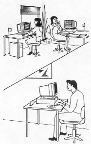
Figure 1-1
WaveLAN in the office
Typical Network
Configurations
The WaveLAN Network Interface Card (NIC) and driver software have been developed for use with common industry-standard networking systems including Novell NetWare and systems supporting the Network Driver Interface Standard (NDIS).
Typical configurations include:
standalone WaveLAN network including one or more servers.
physically separated WaveLAN networks (for example: on different floors of the same building) connected via a wired backbone.
wired network with bridge allowing connection into the network from one or more WaveLAN stations.
a wireless bridge connecting two wired LANs (overcoming physical obstacles to a wired connection).
WaveLAN Components
The WaveLAN adapter kit contains the basic set of components required to install WaveLAN in a personal computer. It includes:
WaveLAN Network Interface Card.
Omni-directional Antenna Module.
WaveLAN Software.
Installation & Operation guide (this book).
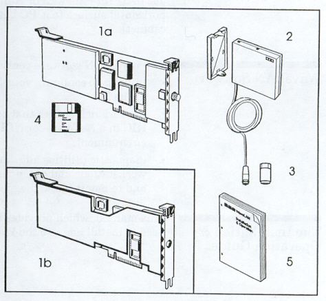
Figure 1-2
WaveLAN Components
1a - WaveLAN 915 MHz card
1b - WaveLAN 2.4 GHz card
2 - Antenna and mounting bracket
3 - Antenna connection tool (915 MHz card only)
4 - WaveLAN software
5 - Installation and Operation guide
The Network Interface Card
The Network Interface Card (NIC) is a printed circuit board which acts as an interface between your personal computer and the rest of the network. The NIC is installed in a board slot inside the PC. It contains a radio-frequency modem in addition to
the circuitry needed to process the signals exchanged between your PC and other stations on the network. The NIC also contains sockets for the optional Boot ROM and Encryption features.
The Omnidirectional Antenna module
The Omni-directional Antenna module attaches to the NIC via a short coaxial cable. The module is accompanied by a mounting bracket which you can use to fix it to the wall or stand it upright on a flat horizontal surface (e.g. PC base, desktop or filin
g cabinet).
WaveLAN software
The WaveLAN software consists of:
utilities to configure your NIC after it is installed in the PC.
network driver files that enable you to use your NIC in a NetWare- or NDIS-compatiable environment.
diagnostic utilities allowing you to position workstations and antennas for best performance, and to monitor and diagnose your network.
The Installation &
Operation Guide
This manual, which provides the information you need to install and use the WaveLAN card.
Feature Options
Optional WaveLAN components include:
Remote Boot ROM for NetWare feature kit. This feature allows a network station to boot from the server.
Security Feature Kit (DES or AES). The Security feature uses the Data Encryption Standard (DES) or the Enhanced Encryption Security Scheme (AES) to provide extra network security by encrypting all data transmitted on the network.
Directional Antenna Kit for inter-facility communications up to 5 miles (8 km.) range (available for the 915 MHz card only).
9-meter (30 ft.) Antenna Extension cable kit for use in areas of excessive local interference (available for the 915 MHz card only).
Preparing for Installation
What You Need
To install a WaveLAN network station, you must have the following:
a Micro Channel compatiable personal computer with a free card slot.
a Reference Diskette for the PC.
MSDOS version 3.0 or higher
(Optionally) OS/2 version 1.2x or higher.
one of the following networking operating environments:
- NOVELL NetWare version 2.1x or higher, version 3.1x or NetWare Lite.
- Any network operating system supporting the NDIS standard. Examples include: LAN Manager 2.0, LAN Server 1.3 and FTP Software Inc.'s PC/TCP.
the basic WaveLAN component set, described earlier.
the appropriate tool for removing the cover of your PC.
Installation Steps
1. Install the WaveLAN Card.
Install optional features on the WaveLAN Network Interface Card, install the card in a personal computer, and configure the Micro Channel system. Connect the antenna. This step is described in Chapter 2.
2. Set the Network Configuration Parameters.
Run the Configuration Setup Utility to create a Card Configuration diskette. You need to do this only once per network. This step is described in Chapter 3.
3. Configure the WaveLAN card.
Using the Card Configuration Diskette, run the Configuration Install Utility to install the Network Configuration parameters on each WaveLAN card. This step is also described in Chapter 3.
4. Test the Communications Path (optional).
When you have installed at least two WaveLAN cards, and before you have installed any network drivers, you can run the Point-to-point Diagnostics utility to check out your WaveLAN installation. Using the Point-to-point Diagnostics utility is described
in Chapter 5.
5. Install the Network Drivers.
Install or generate a network driver. The procedure is different for each network operating system.
Appendix A provides information about installing NetWare drivers.
Appendix B provides generic information about installing the WaveLAN NDIS driver, and some examples using LAN Manager, StarLAN, LAN Server and PC/TCP.
Before you begin
Use the MSDOS Diskcopy command to create a working copy of your WaveLAN diskette. Use your working copy in all card configuration and driver installation procedures. Store the original file in a safe place.
Preparing the Network Interface Card
This section explains how to prepare the WaveLAN NIC before you install it in your PC. Preparation includes installing optional features and setting the hardware configuration switches.
Warning!
Static electricity can severly damage the interface card. To prevent damage when unpacking and handling the interface card, you should make sure to discharge the excess static electricity from your body. You can do this by touching an earthed metal surface such as the chassis of your PC.
- Carefully open the antistatic shipping bag the card comes in, and remove the card. When handling the card don't touch any of the components on its surface or the edge connectors along the bottom of the card. Follow these guidelines always whenever you handle the card.
- Lay the interface card down on a flat surface on top of the antistatic bag.
Installing Optional Features
Optional features which you should install before placing the card in the PC include:
- The Remote Boot ROM feature
- The Security Feature
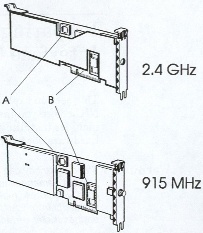
Figure 2-1
Feature Options and Switch Locations
A - Security Chip
B - Boot ROM
Installing the Remote Boot Feature
If you are going to install The Remote Boot ROM on the WaveLAN card, proceed as follows:
- Following the precautions described earlier about static electricity, carefully remove the Boot ROM from its antistatic packaging.
- Examine and familiarize yourself with the chip and the socket where it will be installed (see Figure 2-2). Make sure none of the connection pins are bent.
- Make sure the chip is correctly aligned: the notch at one end of the chip should line up with the notch in the socket.
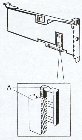
Figure 2-2
Installing the Boot ROM
A - Alignment Notches
- Holding the chip lengthways between finger and thumb, engage the pins on one side with the corresponding row of holes in the socket, and gently manipulate the chip until the pins on both sides are engaged. Carefully push the chip into its socket.
Installing The Security Feature
If you are going to install the Security Feature, proceed as follows:
- Following the precautions described earlier about static electricity, carefully remove the encryption chip from its antistatic packaging.
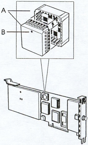
Figure 2-3
Installing the Security Feature
A - Alignment Notches
B - Pin 1 Position Marker
- Examine and familiarize yourself with the chip and the socket where it will be installed (see Figure 2-3). Note the arrow embossed on the base of the socket and the dot in the middle of the bevelled edge marking the position of pin 1. Note also the keyed corner of the chip and its corresponding socket.
- Make sure the chip is correctly aligned, with the arrow in the socket base pointing to the dot marking the pin 1 position and the keyed corners in line.
- Carefully push the chip into its socket.
Installing the Interface Card in your Personal Computer
The following directions apply to most PCs. See your PC owner's manual for more details on how to install an adapter board.
Warning!
Static electricity can severly damage the interface card or any other boards in the PC. Before attempting to insert the card into the PC you should make sure to discharge the excess static electricity from your body. You can do this by touching an earthed metal surface such as the chassis of your PC (before unplugging the power cord).
- Park the disk drive heads.
If your PC has a fixed disk which is not self-parking, use a head-parking utility to park the disk drive heads. This reduces the likelyhood of damage to the disk surfaces.
- Turn off the power switch and disconnect cables.
Turn off the power to your PC and any attached devices. Disconnect the power cord and any other cables.
DANGER!
Do not attempt to install the interface card without disconnecting the power cord and other cables from your personal computer. If you fail to take this precaution, you could recieve a severe electrical shock or cause damage to your personal computer.
- Remove the cover of your personal computer.
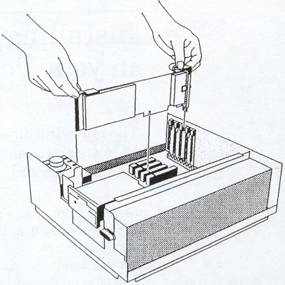
Figure 2-5
Inserting the 915MHz card in a PC
Refer to your personal computer owner's manual for specific instructions about removing the cover.
- Select an unused expansion slot.
Prepare the expansion slot to hold your Network Interface Card by removing the slot's cover plate.
- Insert the Interface Card
Align the edges of the card with the expansion slot and gently press on the top of the card until the edge connector is seated in the slot (see Figure 2-5). When the card is properly inserted, tighten the retaining screw securely.
- Install a second Network Interface Card (optional).
If you want to install a second card, repeat steps 4 and 5.
- Note the Slot Number(s) used.
Make a note of the slots you used to install the card(s). You may need this information for Card Configuration and/or Driver Installation.
- Reinstall the cover and reattach the cables.
After you insert the Network Interface Card, reattach the PC's cover. Move your PC to its intended location, and reattach the power cord and other cables you disconnected earlier.
Connecting the 2.4 GHz Antenna
To connect the antenna to the 2.4 GHz card, simply push the cable end connector on to the connector situated in the middle of the card's end bracket until it clicks into place.
Connecting the 915 MHz Antenna
The 915MHz card's antenna cable is fitted with a male F-type connector which is screwed directly onto the female connector protruding from the WaveLAN card end bracket. Screw the antenna cable connector on to the card's antenna connection until hand-tight. On some PC's you may have difficulty doing this with fingers alone. In that case use the antenna attachment tool provided. Slip this (large end first) over the cable connector and push the connector through until it seats snugly in the tool (the connector should protrude about 2 mm. from the small end of the tool). You can now use the attachment tool to screw the cable connector home (Note: The tool remains on the cable after fitting).
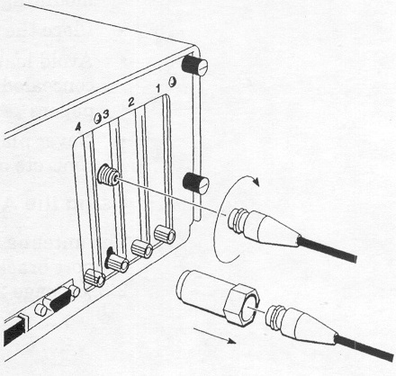
Figure 2-6
Attaching the Antenna to the 915 MHz card
Antenna Placement
The antenna performs best in an open environment with as few obstructions as possible. Signal strength can be significantly affected by closeness to metal surfaces and, to a lesser extent, by concrete walls, thick masonry walls and solid high-density materials. To ensure the best performance:
Position the antenna at right angles to the mounting surface whereever possible
Place the antenna above a desk rather than below
Avoid leaving the antenna where it may be concealed by working materials such as books or papers
Never place the antenna against a metal, concrete or masonry surface
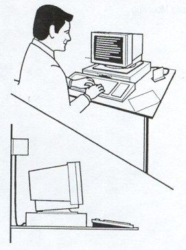
Figure 2-7
Typical Antenna Positions
Using the Antenna Support Bracket
The antenna module is constructed to snap to its support bracket in one of two positions (see Figure 2-8).
At its edge, taking a position at right angles to the support bracket. This is the normal fixing method, allowing the antenna module to hang from a vertical surface or stand on a horizontal one.
At its midpoint, allowing the module to sit flat against the support bracket. This method is suitable for windows and light hollow partitions. It is not recommended for metal, concrete, masonry or solid wood surfaces.
You can fix the support bracket to a vertical surface in one of two ways:
with plugs and screws provided. This method is recommended for concrete and masonry walls, papered of with a rough surface.
with Velcro fastening strips. Use this method for smooth hollow surfaces such as half-height office dividing walls and filing cabinets, or windows.
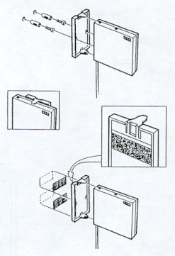
Figure 2-8
Fixing the Antenna Mounting Bracket
More to follow...